The Wavedrum Oriental is a wonderful electronic instrument. Unlike an electronic drum set or drum machines with touch sensitive pads, this drum synthesizer’s sensors don’t merely trigger samples. The sensors rather behave like microphones or the pickup in an electric guitar; the signals of the four sensors—one sensor for the drum head, one sensor on the left and another on the right of the metal rim, and a pressure sensor in the centre of the drum—are used to control drum synthesizer algorithms whose output can be mixed with PCM samples. As a result, the instrument feels a lot like a real drum, a feat that cannot easily be achieved with devices that use simple velocity-sensitive sample triggers.
For all its magic, the Wavedrum also has a number of flaws. Most prominently, all editing is done through five buttons and an endless rotary encoder. What parameters can be selected by the buttons and thus manipulated by the encoder depends entirely on context; one button is used to jump to the next parameter page; simultaneously pressing a pair of buttons switches between the two edit modes (why two?), “global” mode and “live” mode; as one navigates through this confusing environment, a three-character seven-segment display conjures up magic strings that occasionally resemble abbreviations of what appear to be parameter names. Without a copy of the manual lying next to the device, any attempt at deciphering the cryptic three-character hints is doomed to fail.
Another painful flaw is the lack of connectivity. There is no way to export these precious custom programmes that were edited with so much difficulty. There is no way to back up the programmes, nor can one share programmes with another Wavedrum. When the device dies, all custom patches go down with it. Or so it seemed.
Not really knowing what to look for I opened up the Wavedrum in the hopes of finding something that would allow me to extend the feature set of the instrument. I first took off the control panel. Only three screws have to be loosened to lift the front panel and look underneath. The PCB, however, does not offer much of interest.
Much more interesting is the main board which is located right underneath the drum head. Removing the rim and the drum head apparently is a permitted activity which does not void the warranty—the manual includes instructions on how to change the drum head.
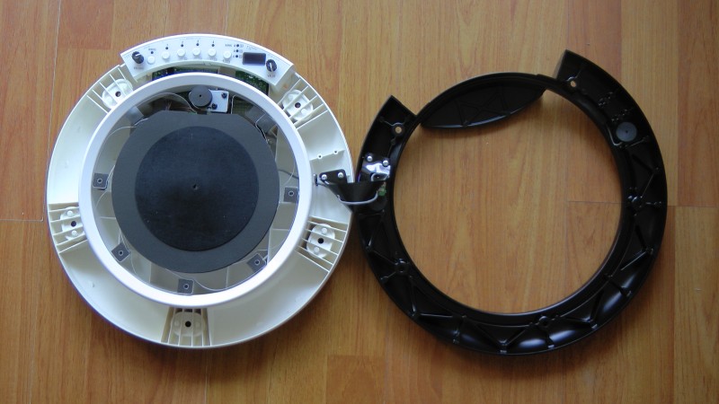
Once the rim and drum head are out of the way, one can already see much of the main board, but access is denied by a transparent plastic disk. In my instrument the plastic disk was only screwed to two posts although there are holes for seven screws. The heads of the two screws are covered with adhesive pads that can easily be removed to undo the screws. (Don’t worry, the glue on the pads is strong enough to put them back on when you’re done.)
With this warning out of the way, let’s move on.
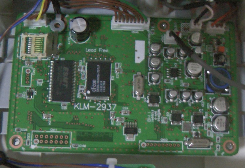
The main board is very tidy making it easy to understand what’s going on. The densely packed section on the right appears to be power supply and rim sensor amplification logic. On the left you can see two medium-sized chips, a bulky capacitor and something covered with a black, textured tape. The two chips are RAM (ESMT) and flash memory (cFeon), respectively. The big capacitor buffers the power for the two memory chips and the massive DSP on the back of the board. The back side of the board is rather boring as it really only holds the DSP chip (ADSP-21375 by Analog Devices). The board has a somewhat unusually great number of test pads (most of which are connected to ground, used for automated testing) and quite a few connector pads, possibly allowing a hardware debugger to be connected to debug the DSP’s firmware in situ.
What is underneath that black tape on the front, though? This is where things get really interesting (well, to people like me, at least). As I carefully removed the tape I was pleasently surprised to see a micro SD card reader underneath. The card is locked to the reading interface to make sure it stays in place during operation. Unlock it by shifting the metal brace to the right whereupon it can be lifted.
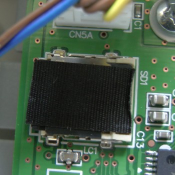
The taped-over SD card
The 2GB micro SD card is a standard card formatted with a FAT32
filesystem, making it possible to read it out with a standard
card reader. My netbook has a built-in SD card reader only, so I
first needed to buy an adapter to connect the micro SD card.
This reader is a little weird. It seems that the adapter must be
in the reader slot on boot or the micro SD card won’t be
recognised. (If you’re unsure whether the card is recognised by
your system check the output of dmesg.) Eventually,
the card was recognised as /dev/sdb1. (/dev/sdb is the SD card reader device itself.) As this is my
only Wavedrum and I intend to use it for years to come I decided
to be especially careful this time and only operate on a copy of the card. The Wavedrum’s card reader is perfectly
capable of reading 8GB micro SD HC cards, so if you want to play
with the data on the card I recommend mirroring the original card
image onto whatever micro SD card you have at your disposal and
play with that instead of the original card. To create a block
level copy of the card I did not mount the filesystem and
simply executed the following command:
dd if=/dev/sdb1 of=wavedrum.imgThis instructs dd to copy all blocks from the input
device file (if, i.e. /dev/sdb1) to the
output file (of) of the name wavedrum.img.
Dependent on the number of disks on your system, the input device
file may have a different name. Check the output of dmesg | tail as you connect the card reader to see which
device node is created for the micro SD card. Note that this
blindly copies everything on the micro SD card, not just
files that are available through the FAT32 filesystem. Hence,
the size of the image is quite a bit larger than the sum of all
files on the mounted image (502,145,536 bytes vs 234,479,878
bytes).
Before continuing, please put the micro SD card back into the Wavedrum’s card reader and lock it to prevent it from being damaged (things can get messy, you know). Going forward, we only need to mount the image to access the data stored on the card. Run the following as root to mount the card image as a read-only filesystem:
mkdir wavedrum
mount -o loop,ro wavedrum.img wavedrum/
Let’s take a look at the files on the card:
The files in the Factory directory contain
initialisation data. When a factory reset is performed, the
customised versions of these files in the root directory are
overwritten with the versions contained in the Factory
directory. All initial programmes that come with the Wavedrum
are stored in Factory/F_PROG.BOR; once programmes have
been edited WD2_PROG.BOR in the root directory will
differ from Factory/F_PROG.BOR. (More about the nature
of these differences later.) PRE_PROG.BOR is the same
as Factory/F_PROG.BOR and is probably used to make the
original factory presets available in addition to custom
programmes, starting at position P.00, the programme
slot after 149.
The initial mapping of presets to any of the 12 slots (3 banks
with 4 slots each) is stored in Factory/F_USER.BOR.
Initially, USER.BOR in the root directory will be
identical to this file. The format of this file is rather
simple:
00000000 |  00 00 00 64 00 00 00 67  00 00 00 7b 00 00 00 6c
00000010 |  00 00 00 65 00 00 00 68  00 00 00 71 00 00 00 7a
00000020 |  00 00 00 84 00 00 00 8c  00 00 00 8b 00 00 00 95
00000030 |  00 00 00 00 00 00 00 00  00 00 00 75 00 00 00 26
00000040 |  00 00 00 07 00 00 00 14  00 00 00 07 00 00 00 14
00000050 |  00 00 00 05 00 00 00 64
Every 8 digit block (4 byte) is used for one slot. We can see that the first slot in bank A is set to programme 100 (0x64 hex), the second to programme 103 (0x67 hex) and so on. As the Wavedrum only allows for 12 slots to store programme identifiers, only the first 48 bytes are used for programmes. The remaining 40 bytes (starting at 0x30) are used for global parameters that can be adjusted in “global” editing mode. The global parameters are stored in this order:
I don’t know yet what purpose F_INST_H.BOR and F_INST_R.BOR serve, but it is clear that the former relates to
settings for the drum head while the latter contains similar
settings for the rim. Even after editing a few programmes,
INST_H.BOR and INST_R.BOR in the root
directory were still identical to their counterparts in the
Factory directory.
The CALIB.BOR appears to contain calibration
information for the head and rim sensors. This is different from
the calibration performed by adjusting the four global paramaters
for sensor threshold and sensitivity. I have not been able to
edit these settings through the Wavedrum so far, so these
probably are factory settings.
All files in the LOOP directory as well as WD2_DATA.BOR contain raw audio data. Unfortunately, I haven’t
quite figured out the format yet, but you can listen to the
clearly recognisable loop patterns with play (part of
the SoX applications):
find LOOP -name "*.BIN" -print |\
  xargs -I XXX \
  play -t raw -r 48k -b 16 -e signed-integer -c 1 XXX
Obviously, this isn’t quite correct. I’m interpreting every 16 bits as a sample in signed integer format, but the sound is distorted and far from the realistic instrument sound when playing back the loops through the Wavedrum.
All loops start with this 44 byte long header:
04 dc 10 d3 uU vV 5W 95  01 d4 00 d0 30 f8 22 b5
46 95 56 95 57 95 57 95  d6 2e 56 95 56 e2 57 95
54 95 46 95 32 f4 22 f4  xX yY 5W 95
With a few exceptions (namely 0009, 0025, 0027, 0030, 0033, 0036, 0049, 0054, 0064, 0082, 0091, 0103, 0104, 0107, 0108, 0127, 0128, 0129, 0130, 0131, 0132, 0135), vV equals yY in most loops. It seems that loops with the same number of bytes have the exact same numbers for uU, vV, W, xX, and yY. This is especially apparent in the loops 0127 to 0132 (inclusive), which are all 192,010 bytes long and all have the values 54:7b:54 for uU:vV:5W and 88:78:54 for xX:yY:5W.
Clearly, more work is required to figure out the complete format of these loop files. Once this is understood we could use custom loops with the Wavedrum.
The raw audio data in WD2_DATA.BOR suffers from the
same problems. Although the data can be interpreted as raw
audio, the sound is distorted and playback is unnaturally fast.
I don’t know what SYSTEM/WDORS110.BIN is used for. The
only useful string contained in the file is “BOOTABLE”. Your
guess is as good as mine as to what it does.
SYSTEM/VERSION.INF is only 16 bytes short and pretty
boring as it contains just what the name implies: version
numbers.
02 02 01 10 02 02 00 00 57 44 4f 52 00 00 00 00This string of numbers is interpreted as follows: firmware
version 2.02, sub-version 1.10, data version 2.02 (followed by
two empty bytes); 57 44 4f 52 (hex for “WDOR”) stands for
“Wavedrum Oriental” (followed by four empty bytes). You can have
the Wavedrum display all its version numbers by pressing the
button labelled “Global” when powering on the device. Note that
the file name WDORS110.BIN references the version
number 1.10, while WDORM202.BIN references the firmware
version number 2.02.
SYSTEM/WDORM202.BIN contains the firmware of the
Wavedrum Oriental. There are many interesting strings and binary
patterns in the file, but I’m still a long way from understanding how it works. To view the strings with the
strings command, you have to specify the encoding as
32-bit little endian:
strings --encoding L SYSTEM/WDORM202.BINSome of the strings embedded in the firmware are file names, some of which are not available on the micro SD card. This includes the following files: SYS00000.BIN, SYS00100.BIN, SYSTEM/WDORS100.BIN, SYSTEM/WDX_M100.BIN, SYSTEM/WDX_S100.BIN, and SUBXXXXX.BIN (a pattern?).
Looking at the hexdump of the file WD2_PROG.BOR which
holds all custom presets, I couldn’t find any obvious patterns in
the file, so I resorted to editing a single programme, setting
particular consecutive parameters to easily recognisable
sequences of values (such as 100, 99, 98, and 97 for hd1, hd2,
hd3, and hd4) and locating the changes in the hexdump.
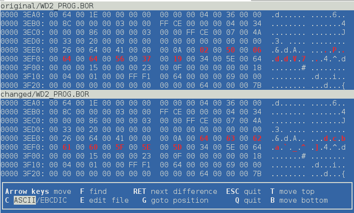
This procedure has allowed me to figure out in what order the parameters are stored in the file. Each programme is exactly 54 16-bit words long; each parameter takes up exactly 16 bits. Negative values are stored in two’s complement format (e.g. negative six is stored as 0xFFFA). The file is exactly 16200 bytes long which is just enough to hold 150 custom programmes, each taking up 108 bytes.
I’m currently writing a Haskell library to parse / build progammes and parameters. The code is available for free here under the GNU GPLv3.
The parameters are stored in this order:
| identifier | mode | target | name |
|---|---|---|---|
| 07.1 | Edit 1 | head algorithm | Pressure curve |
| type | Edit 2 | – | Pre EQ |
| 01.1 | Edit 1 | head algorithm | Tune |
| 02.1 | Edit 1 | head algorithm | Decay |
| 03.1 | Edit 1 | head algorithm | Level |
| 04.1 | Edit 1 | head algorithm | Pan |
| 05.1 | Edit 1 | head algorithm | Algorithm select |
| hd.1 | Edit 2 | head algorithm | Algorithm parameter 1 |
| hd.2 | Edit 2 | head algorithm | Algorithm parameter 2 |
| hd.3 | Edit 2 | head algorithm | Algorithm parameter 3 |
| hd.4 | Edit 2 | head algorithm | Algorithm parameter 4 |
| hd.5 | Edit 2 | head algorithm | Algorithm parameter 5 |
| hd.6 | Edit 2 | head algorithm | Algorithm parameter 6 |
| hd.7 | Edit 2 | head algorithm | Algorithm parameter 7 |
| hd.8 | Edit 2 | head algorithm | Algorithm parameter 8 |
| 01.3 | Edit 1 | rim algorithm | Tune |
| 02.3 | Edit 1 | rim algorithm | Decay |
| 03.3 | Edit 1 | rim algorithm | Level |
| 04.3 | Edit 1 | rim algorithm | Pan |
| 05.3 | Edit 1 | rim algorithm | Algorithm select |
| rm.1 | Edit 2 | rim algorithm | Algorithm parameter 1 |
| rm.2 | Edit 2 | rim algorithm | Algorithm parameter 2 |
| rm.3 | Edit 2 | rim algorithm | Algorithm parameter 3 |
| rm.4 | Edit 2 | rim algorithm | Algorithm parameter 4 |
| rm.5 | Edit 2 | rim algorithm | Algorithm parameter 5 |
| rm.6 | Edit 2 | rim algorithm | Algorithm parameter 6 |
| rm.7 | Edit 2 | rim algorithm | Algorithm parameter 7 |
| rm.8 | Edit 2 | rim algorithm | Algorithm parameter 8 |
| 01.2 | Edit 1 | head PCM instrument | Tune |
| 02.2 | Edit 1 | head PCM instrument | Decay |
| 03.2 | Edit 1 | head PCM instrument | Level |
| 04.2 | Edit 1 | head PCM instrument | Pan |
| 05.2 | Edit 1 | head PCM instrument | PCM instrument select |
| 06.2 | Edit 1 | head PCM instrument | Velocity curve |
| 07.2 | Edit 1 | head PCM instrument | Pressure curve |
| 08.2 | Edit 1 | head PCM instrument | Pressure tune |
| 09.2 | Edit 1 | head PCM instrument | Pressure decay |
| 01.4 | Edit 1 | rim PCM instrument | Tune |
| 02.4 | Edit 1 | rim PCM instrument | Decay |
| 03.4 | Edit 1 | rim PCM instrument | Level |
| 04.4 | Edit 1 | rim PCM instrument | Pan |
| 05.4 | Edit 1 | rim PCM instrument | PCM instrument select |
| 06.4 | Edit 1 | rim PCM instrument | Velocity curve |
| 07.4 | Edit 1 | rim PCM instrument | Pressure curve |
| 08.4 | Edit 1 | rim PCM instrument | Pressure tune |
| 09.4 | Edit 1 | rim PCM instrument | Pressure decay |
| 10.1 | Edit 1 | – | Reverb type |
| 10.2 | Edit 1 | – | Reverb effect level |
| 10.3 | Edit 1 | – | Reverb decay time |
| 10.4 | Edit 1 | – | Reverb frequency damping |
| 11.3 | Edit 1 | – | Delay feedback |
| 11.2 | Edit 1 | – | Delay effect level |
| 11.1 | Edit 1 | – | Delay time |
| 11.4 | Edit 1 | – | Delay frequency damping |
The following tools have proven indispensable in the analysis:
base and base2 functions)If you own an earlier model of the Wavedrum or the latest Wavedrum Global Edition, I would be very happy if you could send me a block-level copy of the SD card (see above for instructions). This would allow me to understand the firmware better and maybe even make it possible to upgrade an older Wavedrum to the latest version (taking into account possible hardware differences, such as differing memory size).
Please send a link to the micro SD card image to .
Comments? Then send me an email! Interesting comments may be published here.